DLC film was deposited in the long tube by pulsed DC PECVD process
The introduction
As a means of fluid transportation, the inner surface of pipeline is often exposed to complex media. Contaminants or corrosive elements present in these fluids will cause corrosion and damage to the inner wall of the pipeline, which will cause huge economic losses every year. At present, researchers have prepared DLC coatings on the inner surface of short and small tubes using plasma discharge methods, and great progress has been made in improving wear, friction, and corrosion properties. However, since these coatings are usually prepared in conventional vacuum chambers, it is impractical to use them to prepare films on the inner wall of long tubes longer than the length of the vacuum chamber, so long tube coating remains a great challenge.
Dot eyeball
Diamond-like carbon (DLC) films were prepared on the inner surface of metal tubes (200cm in length, 10cm in diameter) by pulsed DC PECVD deposition. The experimental results show that stable discharge can be established in the tube. When different gas discharge is used, the tube surface temperature forms different gradients; The growth rate and structural properties of DLC films vary with the axial direction of the tube.
content

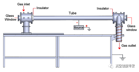
FIG. 1 Schematic diagram of the device
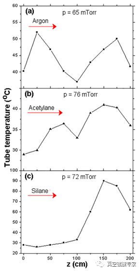
FIG. 1 shows the coating equipment on the inner wall of the tube. The gas enters from the left end and is pumped out from the right end. This is shown in Figure 2. The temperature varies depending on the type of gas used. When the argon plasma is discharged, a distribution shape similar to the letter M is formed along the tube axis, FIG. 2(a). Figure 2(b) acetylene plasma temperature curve and Figure 2(c) silane plasma temperature curve. It is observed that the profile changes significantly in the z>150cm region, and the temperature increases greatly when the silane plasma is discharged.

FIG. 2 Pipeline temperature distribution curves after different gas discharges

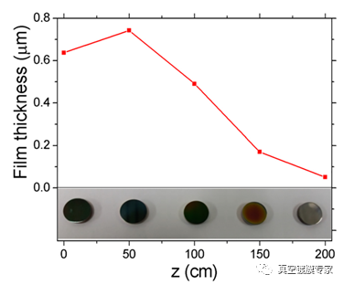
FIG. 3 Film thickness at different positions in the tube
This is shown in Figure 3. The thickness of the film changes along the direction of the gas flow. According to the position of the tube axis, the deposition layer with Z=0cm is about 0.6μm, and the deposition layer with Z=200cm decreases to 0.05μm along the direction of the gas flow. Based on the above results, it is concluded that the inhomogeneity of the film thickness is very obvious along the length of the tube and the direction of the gas flow. It shows that the uniformity of film deposition is affected by the way of air intake and the length of pipeline.
FIG. 4 Raman analysis results of the film layer
Raman detection analysis was performed to determine the characteristic peaks related to the D and G bands of the Raman spectrum of the film layer. After analysis, the displacement of G peak position and the information of I(D)/I(G) ratio are obtained, as shown in FIG. 4. When G position changes between 1528 and 1558cm-1, the ratio of I(D)/I(G) changes from Z =0cm to Z =200cm according to the sample position. The decrease of G peak to the lower position is caused by the change of Sp3 content, which indicates that the graphite proportion in the film is decreasing and the hardness of the film is increasing.
conclusion
The tube temperature and the basic characteristics of DLC film growth in the deposition process of DLC film prepared in tubes with large aspect ratio were comprehensively analyzed. The results show that the plasma discharge in the tube is stable, but there are some characteristics :(a) the discharge causes the tube temperature to rise, forming a symmetric distribution similar to m-shape; (b) When discharging in the precursor gas, the tube temperature is severely affected, resulting in uneven distribution, which is caused by the impact of plasma on the tube surface and the pressure drop of gas along the tube axis. Under these conditions, the growth rate and structure of DLC films are affected.
 0769-81001639
